Introduction to Surface Roughness
Surface topography is of great importance in specifying the function of
a surface. A significant proportion of component failure starts at the
surface due to either an isolated manufacturing discontinuity or gradual
deterioration of the surface quality. Typical of the former is the laps
and folds which cause fatigue failures and of the latter is the grinding
damage due to the use of a worn wheel resulting in stress corrosion and
fatigue failure. The most important parameter describing surface integrity
is surface roughness. In the manufacturing industry, surface must be within
certain limits of roughness. Therefore, measuring surface roughness is
vital to quality control of machining work piece. Below are the definition
of surface roughness and its main measurement methods.
Description of Surface Roughness
The roughness of a surface can be measured in different ways which are
classified into three basic categories:
-
Statistical descriptors that give average behavior of the surface
height. For example, average roughness Ra; the root mean square roughness
Rq; the skewness Sk and the kurtosis K.
-
Extreme value descriptors that depend on isolated events. Examples
are the maximum peak height Rp, the maximum valley height Rv, and the maximum
peak to valley height Rmax.
-
Texture descriptors that describe variations of the surface based
on multiple events. An example for this descriptor is the correlation length.
Among these descriptors, the Ra measure is one of the most effective surface
roughness measures commonly adopted in general engineering practice. It
gives a good general description of the height variations in the surface.
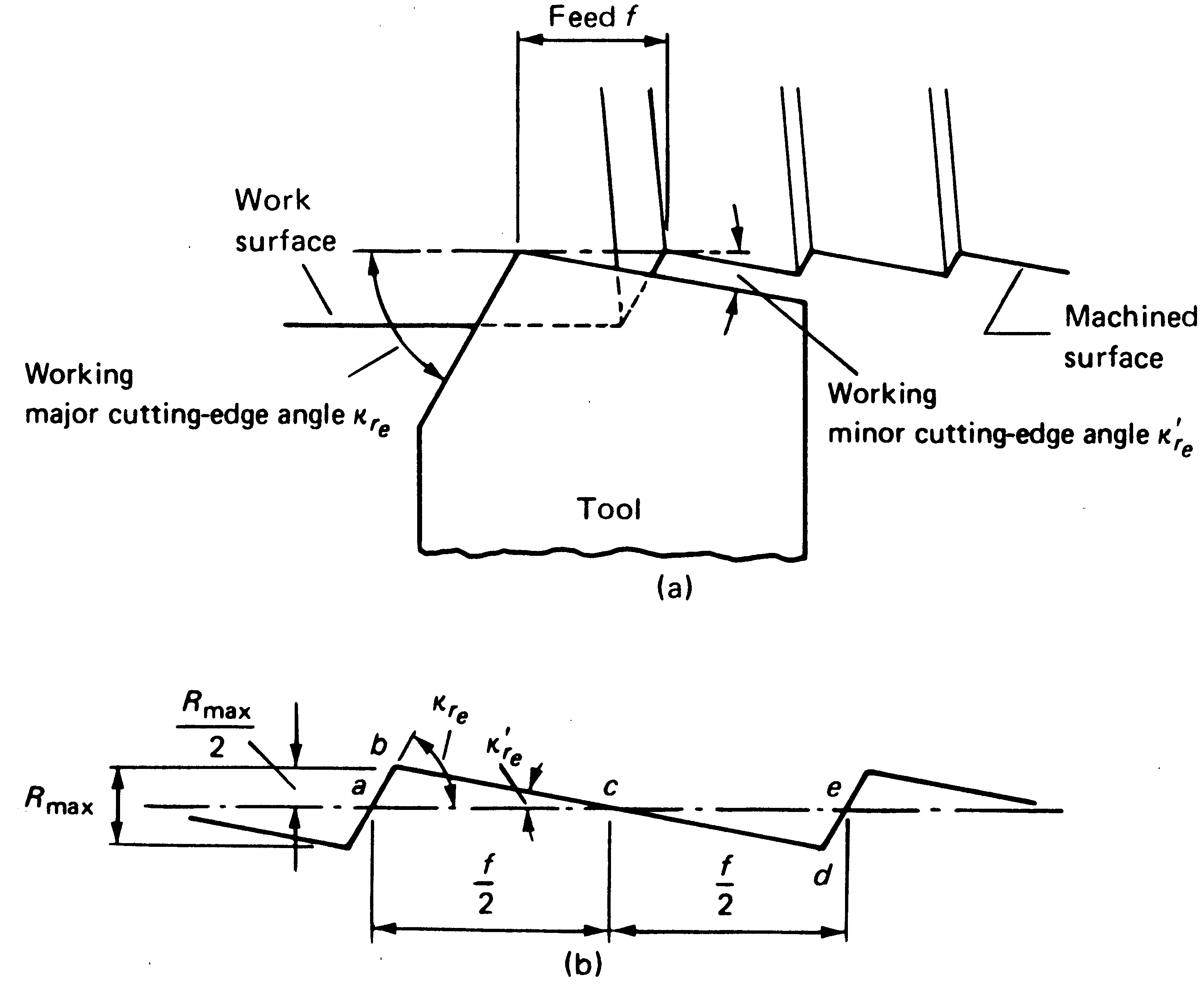
The following figure shows a cross section through the surface , a mean
line is first found that is parallel to the general surface direction and
divides the surface in such a way that the sum of the areas formed above
the line is equal to the sum of the areas formed below the line. The surface
roughness Ra is now given by the sum of the absolute values of all the
areas above and below the mean line divided by the sampling length. Therefore,
the surface roughness value is given by
Ra=(|area abc|+|area cde|)/f.
where f is the feed.

Main Measurement Methods of Surface Roughness
Inspection and assessment of surface roughness of machined workpieces can
be carried out by means of different measurement techniques. These methods
can be ranked into the following classes:
Direct Measurement Methods
Direct methods assess surface finish by means of stylus type devices. Measurements
are obtained using a stylus drawn along the surface to be measured: the
stylus motion perpendicular to the surface is registered. This registered
profile is then used to calculate the roughness parameters. This method
requires interruption of the machine process, and the sharp diamond stylus
may make micro-scratches on surfaces.
Comparison Based Techniques
Comparison techniques use specimens of surface roughness produced by the
same process, material and machining parameters as the surface to be compared.
Visual and tactile senses are used to compare a specimen with a surface
of known surface finish. Because of the subjective judgment involved, this
method is useful for surface roughness Rq>1.6 micron.
Non Contact Methods
There have been some work done to attempt to measure surface roughness
using non contact technique. Here is an electronic speckle correlation
method given as an example.
When coherent light illuminates a rough surface, the diffracted waves
from each point of the surface mutually interfere to form a pattern which
appears as a grain pattern of bright and dark regions. The spatial statistical
properties of this speckle image can be related to the surface characteristics.
The degree of correlation of two speckle patterns produced from the same
surface by two different illumination beams can be used as a roughness
parameter.
The following figure shows the measure principle. A rough surface is
illuminated by a monochromatic plane wave with an angle of incidence with
respect to the normal to the surface, multiscatterring and shadowing effects
are neglected. The photosensor of a CCD camera placed in the focal
plane of a Fourier lens is used for recording speckle patterns. Assuming
Cartesian coordinates x,y,z, a rough surface can be represented by its
ordinates Z(x,y) with respect to an arbitrary datum plane having transverse
coordinates (x,y). Then the rms surface roughness can be defined and calculated.

On-process measurement
Many methods have been used to measure surface roughness in process. For
example:
Machine vision. In this technique, a light source is used to
illuminate the surface with a digital system to viewing the surface and
the data being sent to a computer to be analyzed. The digitized data is
then used with a correlation chart to get actual roughness values.
Inductance method. An inductance pickup is used to measure
the distance between the surface and the pickup. This measurement gives
a parametric value that may be used to give a comparative roughness. However,
this method is limited to measuring magnetic materials.
Ultrasound. A spherically focused ultrasonic sensor is positioned
with a non normal incidence angle above the surface. The sensor sends out
an ultrasonic pulse to the a personal computer for analysis and calculation
of roughness parameters.
Copyright/Source: www.mfg.mtu.edu/cyberman/quality/metrology/surface.html


